Pallet Rack Beam Connector and Locking Pin Inspection: Engagement, Damage and Safety Checks
In a pallet racking system, the connection between a horizontal beam and an upright frame is a critical structural interface. Beam connectors transfer loads into the upright structure, while locking pins or other locking devices help prevent unintended beam disengagement during normal warehouse operations.
Although these components are relatively small compared with the overall rack structure, their condition should never be overlooked. Incorrect engagement, missing locking devices, damaged connector hooks or unauthorized modifications can affect the reliability of the beam-to-upright connection.
This guide explains how warehouse operators, installation teams and maintenance personnel can inspect pallet rack beam connectors and locking pins, recognize common problems and establish a consistent inspection process.
1. Understand the Beam-to-Upright Connection
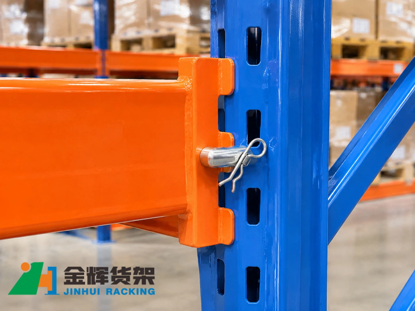
Most adjustable pallet racking systems use mechanical connectors at the ends of horizontal beams. These connectors engage with corresponding slots or connection points in the upright columns.
The exact connection design depends on the rack manufacturer and product series. Common components may include:
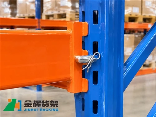
- Beam connector: The end fitting attached to the horizontal beam, designed to engage with the upright connection slots.
- Connector hooks: The projecting elements that engage with the upright column.
- Locking pin or safety clip: A retaining component intended to help prevent accidental beam disengagement.
- Upright connection slots: The openings designed to receive the beam connector.
- Beam end plate: The connector assembly interface attached to the beam end.
Some rack systems use different connector geometries or locking arrangements. Inspection personnel should identify the actual connection type before applying any inspection criteria.
2. Why Beam Connector Inspection Matters
Beam connectors are responsible for maintaining the connection between horizontal beams and upright frames. Their condition and correct engagement are important to the intended performance of the racking structure.
Regular inspection helps identify issues such as:
- Beam connectors that are not fully engaged with the upright.
- Missing, damaged or incorrectly installed locking devices.
- Cracked, bent or visibly deformed connector components.
- Damaged upright slots around the connection area.
- Unauthorized replacement parts or incompatible components.
- Evidence of impact damage or movement around the connection.
Early identification allows the responsible team to assess the condition and arrange appropriate corrective action before the problem becomes more serious.
3. Check Correct Beam Connector Engagement
One of the first inspection tasks is to verify that each beam connector is correctly seated in its corresponding upright connection.
During inspection, check whether:
- All designed connector hooks are engaged with the correct upright slots.
- The beam end is positioned correctly against the upright.
- The connector is not visibly tilted, displaced or partially disengaged.
- The beam is installed at the intended elevation and connection position.
- Both ends of the beam show the correct engagement condition.
Do not assume that a beam is correctly installed simply because it appears horizontal or because one end looks secure. Both beam-to-upright connections should be inspected.
If the connector does not appear to be fully engaged, restrict access to the affected area as appropriate and arrange an assessment by a competent person. Do not attempt to force the connector into position while the beam is carrying a load.
4. Inspect Locking Pins and Safety Devices
Locking pins, safety clips and similar retaining devices are designed to reduce the risk of unintended beam disengagement. Their presence and correct installation should be verified according to the specific rack design.
Inspect each locking device for the following conditions:
- Presence: Confirm that the required locking device is installed at the designated connection.
- Correct type: Check that the device matches the connector and rack series.
- Correct position: Verify that it is fitted in the intended retaining position.
- Physical condition: Look for bending, cracking, corrosion or other visible damage.
- Secure retention: Check that the device is not loose or visibly displaced.
A missing locking pin should not be replaced with an improvised bolt, wire, nail or other unapproved object. Only the specified replacement component should be used.
It is also important to understand that a locking pin does not increase the rated load capacity of a beam or compensate for a damaged connector. Its function is determined by the connection design.
5. Identify Common Connector Damage
Beam connectors can be affected by forklift contact, installation errors, repeated handling, corrosion or unauthorized alterations. Inspection personnel should look for visible changes in component geometry and condition.
5.1 Bent or Deformed Connector Hooks
Connector hooks should retain the geometry specified by the manufacturer. Bent or distorted hooks may not engage correctly with the upright slots.
Any visible deformation should be documented and assessed. Do not attempt to straighten a damaged connector by hammering or heating it unless an approved repair procedure specifically permits the action.
5.2 Cracks or Fractures
Cracks around connector hooks, welds or end plate interfaces require particular attention. A cracked component may no longer provide the intended connection performance.
Where cracking is suspected, the affected connection should be assessed by a competent person. Welding or other repair work should not be carried out without manufacturer or engineering approval.
5.3 Corrosion and Surface Deterioration
Corrosion can affect exposed connector surfaces, especially in humid, cold-storage or chemically aggressive environments. Check for corrosion that may have reduced the component section or affected the connection interface.
Light surface discoloration and significant material loss are not equivalent conditions. The severity should be assessed according to the component material, location and applicable inspection criteria.
5.4 Damaged Upright Slots
Connector inspection should include the corresponding upright connection area. Deformed slots, torn material or damage around the column face can affect the engagement between the beam and upright.
Do not evaluate the connector in isolation when the mating upright area is visibly damaged.
6. Check for Signs of Unauthorized Beam Adjustment
Adjustable pallet racking allows beam elevations to be changed to suit different pallet dimensions and storage requirements. However, beam relocation must follow the manufacturer's instructions and the approved rack configuration.
During inspection, look for:
- Beams installed at elevations that differ from the approved configuration.
- Missing locking devices after beam relocation.
- Mixed connector components from incompatible rack systems.
- Modified connectors or drilled connection holes.
- Unapproved welding, cutting or grinding around the connection.
- Beam arrangements that no longer match the approved load information.
Changing beam elevations can affect the load distribution and the structural configuration of the rack. After a modification, the revised arrangement should be reviewed against the applicable design documentation and load information.
7. Inspect Both Ends of Every Beam
A beam has two connection points, and both must be checked. Inspecting only the more accessible end can leave an important defect unnoticed.
A practical inspection sequence is:
- Identify the rack row, bay and beam level.
- Visually inspect the first beam connector and its locking device.
- Check the corresponding upright slots for visible damage.
- Inspect the opposite beam connector and locking device.
- Compare both connection conditions with the approved rack design.
- Record any missing, damaged, displaced or incompatible components.
Where inspection access is restricted, use an approved access method. Do not climb rack beams or use pallets as an improvised working platform.
8. Common Beam Connector and Locking Pin Problems
| Observed condition | Possible concern | Recommended response |
|---|---|---|
| Missing locking pin | Beam may not have the specified retaining protection | Restrict use as appropriate and install the approved replacement after assessment |
| Connector hook is visibly bent | Correct engagement may be affected | Arrange competent assessment and replace the component if required |
| Beam end is not fully seated | Connection may be incorrectly engaged | Assess the connection and correct the installation using the approved procedure |
| Crack near connector weld | Possible loss of connection integrity | Isolate or restrict the affected area as appropriate and obtain engineering assessment |
| Upright slot is deformed | Mating connector may not engage as designed | Inspect the upright and connector together before returning the bay to service |
| Non-standard replacement pin | Compatibility and retention performance are uncertain | Replace with the specified component after confirming the correct part |
| Evidence of unauthorized welding or modification | Original component properties or connection geometry may have changed | Obtain manufacturer or engineering review before use |
9. Establish a Practical Inspection Record
A consistent inspection record helps maintenance teams track defects, identify recurring damage locations and confirm that corrective actions have been completed.
Recommended inspection record fields include:
- Inspection date and responsible personnel.
- Warehouse location, rack row, bay and beam level.
- Beam connector condition at both ends.
- Locking pin or safety device presence and condition.
- Upright slot and connection-area condition.
- Photographs of visible defects, where appropriate.
- Risk assessment and immediate control measures.
- Required corrective action and responsible party.
- Completion date and verification result.
Where multiple rack types are installed in the same warehouse, records should identify the rack manufacturer or system type. This reduces the risk of using the wrong replacement components during maintenance.
10. Corrective Actions and Replacement Considerations
When a connector or locking device is found to be damaged or missing, the response should be based on the condition, location and manufacturer's requirements.
Depending on the severity, appropriate actions may include:
- Restricting access to the affected bay or area.
- Removing stored loads under a controlled and approved procedure.
- Replacing damaged connectors or locking devices with approved parts.
- Inspecting the mating upright and adjacent structural components.
- Reviewing whether the damage is related to forklift impact or another recurring cause.
- Recording the repair and verifying the connection before returning the area to service.
Do not remove a loaded beam or attempt to replace its connector while the beam is carrying pallets. Any unloading, dismantling or repair work should follow a safe work procedure and be performed by trained personnel.
Replacement components should be compatible with the exact rack system. Similar-looking connectors from another manufacturer or product series should not be assumed interchangeable.
11. Prevent Recurring Connection Damage
Routine inspection is important, but preventing repeated damage is equally valuable. Warehouse operators can reduce the likelihood of connector problems by addressing the causes of impact and incorrect handling.
Useful preventive measures include:
- Training forklift operators to avoid contact with rack uprights and beam ends.
- Maintaining suitable operating clearances in rack aisles.
- Using appropriate rack protection where specified by the design.
- Checking beam connections after approved rack reconfiguration work.
- Keeping compatible replacement locking devices available.
- Including connector and locking pin checks in routine rack inspections.
- Reporting impact events rather than waiting for visible deformation to appear.
Conclusion
Pallet rack beam connectors and locking pins are small components with an important role in maintaining the intended beam-to-upright connection. Regular checks should confirm correct engagement, the presence and condition of locking devices, and the absence of deformation, cracking or unauthorized modifications.
By inspecting both ends of each beam, recording defects and using only approved replacement components, warehouse teams can improve maintenance consistency and identify connection problems before they develop into more serious safety concerns.
Inspection and repair decisions should always follow the rack manufacturer's instructions, the approved system configuration and applicable warehouse safety requirements.
Contact Us
Looking for pallet racking solutions or technical support for your warehouse storage project? Contact our team to discuss rack configurations, component requirements and project-specific applications.
Email: info@jhrack.com
WhatsApp: +86 185 0252 7163