Four-Way Shuttle Racking Rail Alignment: Installation Checks for Accurate and Reliable Shuttle Travel
In a four-way shuttle storage system, rail alignment is a critical part of the mechanical installation. The shuttle relies on accurately positioned running surfaces to travel along storage lanes, change direction at designated transfer points and access the required pallet positions. Even when the rack structure appears straight and level, local rail deviations or poorly connected joints can affect shuttle movement.
Rail installation should therefore be treated as a coordinated engineering task involving the rack structure, rail supports, shuttle dimensions and control-system requirements. This guide explains the main alignment checks to complete before commissioning a four-way shuttle racking system.
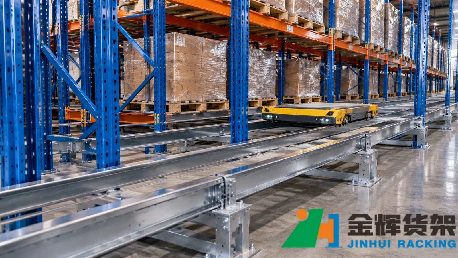
Rail positioning, support conditions and connection quality are important considerations when installing a four-way shuttle racking system.
1. Understand the Rail Arrangement Before Installation
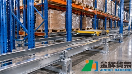
A four-way shuttle system generally uses a coordinated arrangement of running rails that allows the shuttle to travel in two directions. Depending on the system design, the shuttle may move longitudinally along a storage lane and transfer onto a perpendicular path at designated intersections.
The actual rail configuration varies by equipment design. Before installation, the project team should confirm the approved layout drawings, rail sections, support details, transfer locations and shuttle travel directions.
Key information to verify includes:
- Rail layout: The position and direction of each running rail in relation to the storage lanes.
- Rail spacing: The specified distance between the running surfaces, based on the shuttle wheel arrangement.
- Support arrangement: The location and type of brackets, seats or structural supports.
- Transfer intersections: The geometry and connection details where the shuttle changes travel direction.
- End conditions: The required rail termination, travel limits and end-stop arrangements.
Do not determine rail spacing or intersection geometry from visual estimates. These dimensions must follow the approved engineering drawings and the shuttle manufacturer's requirements.
2. Establish a Consistent Reference Datum
Rail alignment should be measured from a clearly defined reference datum rather than from adjacent components that may themselves be out of position. A consistent reference helps installers identify whether deviations are caused by the rack structure, rail supports or the rails themselves.
Before taking measurements, confirm:
- The project survey reference and elevation datum.
- The approved rack centerlines and storage-lane positions.
- The specified rail centerline or running-surface reference.
- The measurement points and inspection sequence.
- The measuring equipment and calibration requirements.
For long storage lanes, measurements should be taken at defined intervals and at critical locations such as rail joints, support points and transfer intersections. Recording the results makes it easier to identify gradual deviations as well as isolated installation errors.
3. Check Longitudinal Rail Straightness
Longitudinal straightness determines whether the rail follows the intended travel path throughout the storage lane. A rail that gradually shifts sideways may reduce the available running clearance or cause inconsistent contact between the shuttle wheels and running surfaces.
Inspect the following conditions:
- Whether the rail centerline follows the approved storage-lane reference.
- Whether the rail remains consistently positioned at intermediate support points.
- Whether local bends, twists or visible deformation are present.
- Whether adjacent rail sections form a continuous travel path.
- Whether rail movement has occurred during tightening or subsequent installation work.
Long straightedges, survey instruments or other approved measuring equipment may be used according to the project inspection procedure. The measurement method should be suitable for the rail length, installation environment and required accuracy.
4. Verify Rail Levelness and Elevation
Rail elevation affects the relationship between the shuttle, the rack structure and the running surfaces. Differences in height between support points can create local steps or uneven running conditions, particularly where rail sections meet.
During inspection, compare measured elevations with the approved installation datum. Pay particular attention to:
- Elevation differences between parallel running rails.
- Changes in rail height along the same storage lane.
- Local high or low points near support brackets.
- Rail elevation at intersections and direction-change areas.
- Changes caused by incomplete seating or incorrect support installation.
Do not assume that a visually level rack beam guarantees correctly aligned shuttle rails. Rail position and elevation should be checked directly at the specified measurement locations.
5. Confirm Rail Spacing and Running Clearance
Rail spacing must match the shuttle's wheel arrangement and the approved system design. Incorrect spacing can affect wheel engagement, available clearance and the shuttle's ability to travel through the intended route.
Measure the distance between the specified rail reference surfaces at representative locations along each lane. Include additional measurements around joints, support brackets and transfer intersections.
Check that:
- Rail spacing is consistent with the approved drawings.
- Parallel rails do not gradually converge or diverge.
- Local spacing changes are not introduced by incorrectly positioned brackets.
- The shuttle's running wheels have the required engagement and clearance.
- Transfer areas maintain the geometry required for the specified direction change.
The acceptable dimensions depend on the shuttle model and rail design. There is no single rail-spacing value suitable for every four-way shuttle installation.
6. Inspect Rail Joints and Connection Details
Rail joints are important inspection points because small differences between adjoining sections can create a discontinuity in the running surface. A connection may appear secure while still having a height difference, lateral offset or gap that requires correction.
Each joint should be checked for:
- Correct positioning of the adjoining rail sections.
- Consistent running-surface elevation across the connection.
- Acceptable lateral alignment and joint gap.
- Correct installation of connection plates and fasteners, where specified.
- Secure support beneath or adjacent to the joint.
- Absence of burrs, sharp edges or visible damage that could interfere with travel.
Fastener type, tightening method and torque requirements must follow the approved installation documentation. Do not apply an assumed torque value or modify a rail connection without engineering approval.
7. Pay Special Attention to Transfer Intersections
Transfer intersections are among the most important areas in a four-way shuttle system. At these locations, the shuttle changes its travel direction or moves between connected rail paths. The rail arrangement must provide the geometry required by the shuttle's transfer mechanism.
Inspection should confirm:
- The intersection matches the approved equipment layout.
- Connecting rail sections are correctly positioned and supported.
- Running surfaces meet without unacceptable steps or offsets.
- The required clearances are maintained around moving components.
- There are no loose fasteners, obstructions or damaged rail edges.
- The transfer area is accessible for the planned inspection and maintenance activities.
Because transfer mechanisms differ between shuttle manufacturers, installers should not improvise intersection details based on the appearance of another system. Use the approved interface drawings and equipment-specific installation instructions.
8. Check Rail Supports and Fixings
Correct rail geometry depends on stable support conditions. A rail may be accurately positioned during initial installation but shift later if its supports or fixing arrangements are incomplete.
Inspect the supporting components as part of the rail alignment process:
- Confirm that each rail support is installed at the specified location.
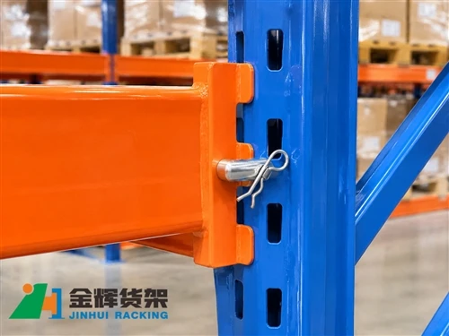
- Check that brackets and seats are correctly oriented and fully seated.
- Verify that specified fasteners are present and properly secured.
- Look for gaps, deformation or damage around support interfaces.
- Confirm that rail supports are compatible with the rack configuration shown in the approved drawings.
Any adjustment to support positions or structural connections should be reviewed against the approved design. Drilling new holes, changing connection details or adding unapproved shims can affect the structural and operational performance of the system.
9. Complete Pre-Commissioning Rail Inspection
Before introducing the shuttle for operational testing, complete a documented inspection of the rail installation. This provides a baseline record and helps prevent mechanical installation issues from being mistaken for control-system or shuttle faults.
A practical inspection checklist includes:
- Approved rail layout and installation drawings are available.
- Reference datum and measurement points are established.
- Longitudinal rail alignment has been measured.
- Rail elevation and levelness have been checked.
- Rail spacing has been verified.
- Rail joints and connection plates have been inspected.
- Transfer intersections have been checked.
- Rail supports and specified fixings are complete.
- End conditions and travel limits match the approved design.
- Inspection results and outstanding corrective actions are recorded.
Where a measurement falls outside the approved acceptance criteria, record its location and measured value, then obtain the required engineering decision before proceeding.
10. Verify Rail Performance During Shuttle Testing
Dimensional inspection should be followed by controlled operational testing under the commissioning procedure. This helps confirm that the installed rail arrangement works with the actual shuttle equipment.
Testing may include:
- Low-speed travel along designated storage lanes.
- Movement through representative rail joints.
- Travel through approved direction-change intersections.
- Checks for abnormal vibration, noise or unexpected contact.
- Verification of shuttle positioning at designated locations.
- Repeated travel tests where required by the commissioning plan.
Testing should be performed by authorized personnel using the manufacturer's commissioning procedure and required safety controls. Do not use operational testing to compensate for unresolved dimensional deviations or visibly defective rail connections.
Common Rail Installation Problems
| Observed condition | Possible installation issue | Recommended action |
|---|---|---|
| Shuttle movement is inconsistent along a lane | Rail straightness, spacing or support position may be incorrect | Recheck the affected lane against the approved datum and drawings |
| Noticeable impact at a rail joint | Possible height difference, gap or lateral offset | Inspect the joint and correct it using the approved connection details |
| Difficulty passing through a transfer area | Intersection geometry or component positioning may be incorrect | Verify the transfer layout and shuttle interface requirements |
| Rail position changes after installation | Support or fixing components may be incomplete or loose | Inspect the support arrangement and specified fasteners |
| Abnormal noise or vibration during travel | Possible rail discontinuity, damage or mechanical interference | Stop testing as required and investigate before further operation |
These observations are diagnostic starting points, not definitive fault conclusions. The actual cause should be established through inspection and the equipment manufacturer's troubleshooting procedure.
Conclusion
Accurate rail alignment is essential to the reliable movement of a four-way shuttle within an automated storage system. Straightness, elevation, rail spacing, joint quality, transfer geometry and support stability should all be checked before commissioning.
A structured inspection process helps identify installation deviations early, reduces avoidable commissioning delays and provides a documented basis for system acceptance. Most importantly, all measurement limits and corrective actions should be based on the approved rack design and shuttle manufacturer's technical requirements rather than assumed universal tolerances.
Contact Us
Planning a four-way shuttle racking project or reviewing the installation requirements for an automated warehouse? Contact our team to discuss your storage system layout, rack configuration and project requirements.
Email: info@jhrack.com
WhatsApp: +86 185 0252 7163