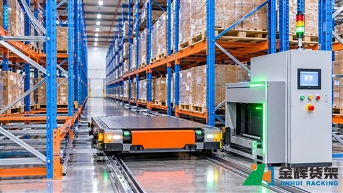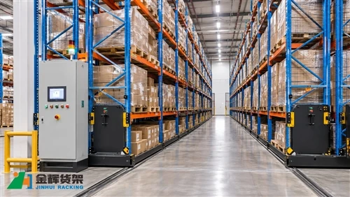
Powered Mobile Racking Safety Interlock Testing: Aisle-Access Sensors, Emergency Stops and Restart Logic
Powered mobile racking systems improve warehouse storage density by moving entire rows of pallet racks along floor-mounted rails. However, because the racks move mechanically and create changing access aisles, their safety controls must be properly configured and tested before the system is handed over for operation.
Safety interlock testing is an important part of commissioning. It verifies whether access detection devices, emergency stops, movement permissions and restart conditions work together as intended. A system should not be considered ready for normal operation simply because the racks can move from one position to another.
This guide explains the main safety functions to review when testing powered mobile racking, how to organize functional checks, and what information should be recorded during commissioning and acceptance.
1. Why Safety Interlock Testing Matters in Powered Mobile Racking
Unlike conventional static pallet racking, powered mobile racking moves on rails to create access to selected storage aisles. During operation, adjacent rack rows may move closer together or separate to open a working aisle.
This movement introduces potential hazards, including:
- People entering an aisle while the adjacent racks are moving.
- Unexpected rack movement during loading or picking activities.
- Obstructions between moving rack rows.
- Unintended restart after an emergency stop or safety interruption.
- Conflicting movement commands from operators or control interfaces.
Safety interlocks are intended to prevent or control hazardous movement under defined conditions. Their actual functions depend on the system design, selected safety devices, control architecture and applicable safety requirements.
Commissioning should therefore verify the complete safety function rather than checking individual sensors or buttons in isolation.
2. Identify the Safety Devices Before Testing
Before functional testing begins, the commissioning team should identify the safety devices installed on the specific mobile racking system. Not every system uses the same arrangement, and the presence of a particular device should never be assumed.
2.1 Aisle-access detection devices
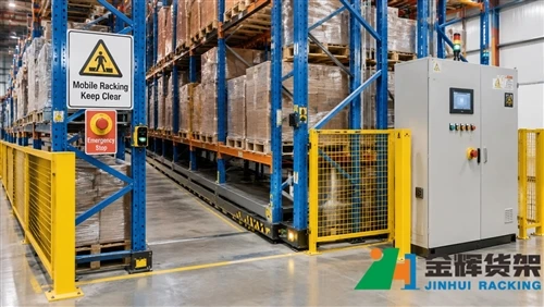
Access detection may use photoelectric sensors, light curtains, safety edges or other devices specified by the manufacturer. Their purpose is to detect a person or obstruction entering a protected area or to prevent movement when access conditions are unsafe.
During inspection, verify:
- The device is installed in the specified position and orientation.
- The sensing area covers the intended protected access zone.
- There are no obvious obstructions, loose brackets or damaged cables.
- The device status is correctly indicated on the control interface, where applicable.
- The device responds according to the approved safety-control design.
2.2 Emergency stop devices
Emergency stop buttons may be installed at designated operator stations, rack ends or other accessible locations, depending on the system configuration.
Inspect each installed emergency stop for accessibility, physical condition, clear identification and secure mounting. Confirm that its operation produces the response specified in the manufacturer's documentation.
An emergency stop should not be treated as a substitute for normal access protection or routine operating procedures.
2.3 Safety edges and obstruction detection
Some powered mobile racking systems use pressure-sensitive safety edges or other obstruction-detection devices along designated rack edges. These devices may be designed to detect contact with an obstruction and initiate a defined stop response.
Check the complete sensing length, mounting condition, wiring connections and response to the manufacturer's prescribed test method. Do not apply excessive force or use improvised objects to trigger a safety device.
2.4 Control cabinet and safety circuit
The control cabinet contains the electrical and control equipment responsible for processing movement commands and safety-related signals. Depending on the design, this may include safety relays, safety controllers, motor control components and communication interfaces.
Verify that electrical drawings, device labels and installed components correspond to the approved project documentation. Any safety-circuit modification should be reviewed and authorized by qualified personnel.
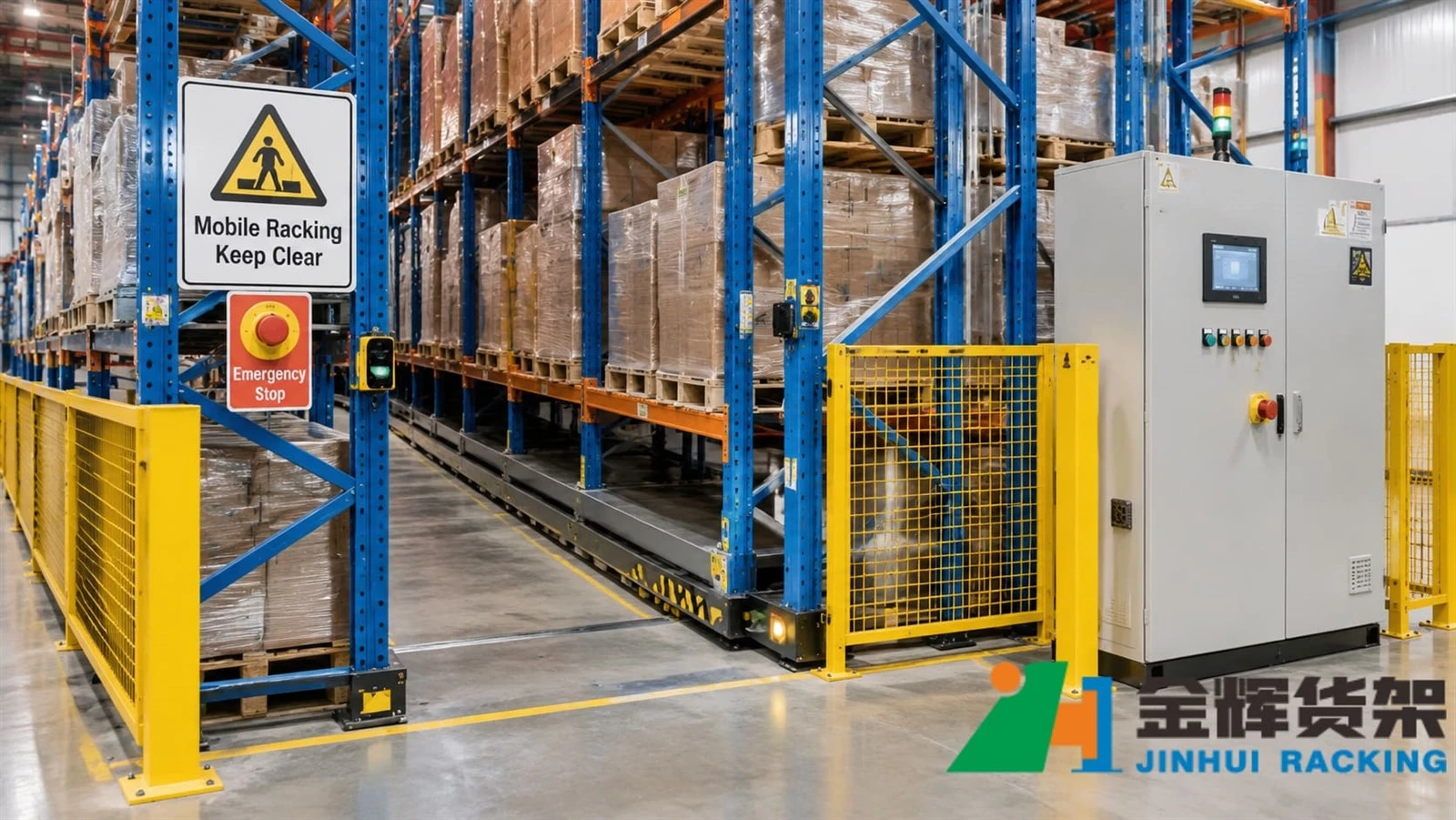
Typical powered mobile racking safety arrangement showing protected access aisles, safety devices and the control cabinet.
3. Establish the Test Conditions Before Commissioning
Safety testing should be performed under controlled conditions. Before activating any movement, the commissioning team should confirm that the installation is ready for functional verification.
Recommended preparation includes:
- Confirming that the rack installation, rail alignment and mechanical stops have been inspected.
- Checking that electrical installation and protective earthing meet the approved design.
- Reviewing the manufacturer's operating and commissioning instructions.
- Confirming that all required safety devices are installed and connected.
- Removing unauthorized personnel from the test area.
- Establishing communication between the operator, commissioning engineer and safety observer.
- Confirming that the test area is free from loose materials and unintended obstructions.
Testing should be conducted by qualified personnel using approved procedures. Where a test requires access to a hazardous area, the relevant isolation and lockout procedures must be followed.
4. Test Aisle-Access Detection and Movement Inhibition
A key commissioning task is to verify how the system responds when an access-protection device detects a person or an obstruction in a protected area.
The exact test method depends on the installed device and the manufacturer's instructions. A typical functional verification sequence may include:
- Confirm that the rack is in a permitted operating condition.
- Check the normal status indication of the access-protection device.
- Use the manufacturer's approved test method to activate the detection device.
- Issue the relevant movement command under the controlled test procedure.
- Verify that the system produces the specified safe response, such as inhibiting movement or stopping movement.
- Check that the control interface indicates the relevant safety condition or fault, where applicable.
- Restore the device using the approved procedure and verify that the system does not restart unexpectedly.
The test should cover each protected access location identified in the approved safety design. A successful test at one aisle does not automatically confirm that every other access point is protected.
5. Verify Emergency Stop Response and Reset Conditions
Emergency stop testing confirms that the installed emergency stop devices can initiate the required stopping response when activated.
For each emergency stop location, record and verify:
- Device identification and physical location.
- Accessibility and visible condition.
- Whether activation produces the specified movement response.
- Whether the relevant control indication changes as designed.
- Whether the emergency stop remains in its actuated state until properly reset.
- Whether resetting the device requires a separate, deliberate restart command.
Resetting an emergency stop should not itself cause hazardous movement. The system should return to an appropriate ready state only after the required reset and restart conditions have been satisfied.
Never bypass an emergency stop circuit to complete a commissioning test or to keep production running.
6. Check Restart Logic After a Safety Interruption
Restart logic is just as important as the initial stopping response. A system may stop correctly when a safety device is activated but still present a risk if it restarts unexpectedly after the device is restored.
Commissioning should therefore verify the complete sequence from safety interruption to controlled return to operation.
6.1 Restoration of the safety condition
After the triggering condition has been removed, check whether the relevant safety input returns to its normal state. Confirm that any required manual reset or acknowledgement is performed according to the system design.
6.2 Separate restart command
Verify whether the control system requires a separate operator command before rack movement can resume. The required sequence should be clearly defined in the manufacturer's operating documentation.
6.3 Movement permission
Before restarting, confirm that the required operating conditions are satisfied. Depending on the installation, these may include access protection status, emergency stop status, aisle selection and other system-specific interlocks.
6.4 Unexpected command prevention
Check that a movement command issued before or during a safety interruption cannot cause unintended movement when the safety condition is restored. The system should follow its approved restart logic rather than automatically executing an old or pending command in an unsafe condition.
7. Verify Coordination Between Safety Devices and Control Logic
Individual devices may function correctly while the overall system still has a coordination problem. For this reason, commissioning should include integrated tests of the safety devices and control sequence.
Depending on the approved design, the following conditions may need to be checked:
- Movement commands are inhibited when the required safety conditions are not satisfied.
- Conflicting movement requests are handled according to the defined control sequence.
- Safety-related signals are correctly processed by the designated control components.
- Fault conditions are indicated clearly enough for operators and maintenance personnel.
- Recovery from a safety interruption follows the specified reset and restart procedure.
Where the mobile racking system interfaces with warehouse management software, warehouse control systems or other automation equipment, confirm that the interface does not override or bypass the designated safety functions.
Operational communication and safety-related control functions should be treated separately according to the system architecture. A normal PLC status signal or software command should not be assumed to provide a safety-rated function unless the design and documentation explicitly establish this.
8. Common Safety Interlock Testing Problems
| Observed issue | Possible area to investigate | Recommended action |
|---|---|---|
| Access sensor does not change status | Device alignment, power supply, wiring or sensor condition | Inspect the device and verify its installation against the manufacturer's instructions. |
| Rack movement is not inhibited as expected | Safety input configuration or control-circuit connection | Stop commissioning and have qualified personnel investigate the approved safety circuit. |
| Emergency stop response is inconsistent | Device condition, wiring or safety-control configuration | Check the affected device and circuit before further operation. |
| System restarts unexpectedly | Reset sequence, restart logic or retained movement command | Keep the system out of service until the restart behavior has been reviewed and corrected. |
| Safety fault indication is unclear | Alarm mapping, HMI configuration or documentation | Verify fault identification and update operator instructions where necessary. |
These are investigation categories rather than instructions to modify safety circuits. Any adjustment, replacement or software change should be authorized, documented and followed by the required retesting.
9. Prepare a Safety Interlock Acceptance Checklist
A structured acceptance record helps ensure that every installed safety function is checked and that unresolved issues are not overlooked during handover.
The following checklist can be adapted to the actual project configuration:
- Approved electrical drawings and safety documentation are available.
- All specified access-protection devices are installed and identified.
- Sensor mounting positions and protected areas have been inspected.
- Access detection functions have been tested using approved methods.
- All installed emergency stop devices have been tested.
- Safety edges or other obstruction-detection devices have been tested where fitted.
- Movement inhibition has been verified under the defined test conditions.
- Reset and restart sequences have been checked.
- Unexpected restart behavior has been assessed.
- Control-system indications and fault messages have been reviewed.
- Outstanding defects have been recorded and assigned for resolution.
- Final test results have been signed off by the responsible personnel.
For traceability, the test record should identify the device, test location, test method, expected response, actual response, result, date and responsible person. Any failed test should be recorded as an outstanding issue and resolved before the affected equipment is released for normal operation.
10. Safety Considerations During Routine Operation
Commissioning acceptance is not the end of safety management. Sensors, cables, emergency stop devices and mechanical protection components may deteriorate or become damaged during warehouse operation.
Warehouse operators and maintenance teams should follow the inspection and maintenance schedule provided by the manufacturer. Routine checks may include visual inspection of safety devices, checking for damaged cables or loose mounting hardware, reviewing recorded safety faults and confirming that operators understand the correct emergency and restart procedures.
Any repeated safety fault, unexpected movement or abnormal stopping behavior should be investigated rather than repeatedly reset. Safety devices should never be covered, disconnected, bypassed or repositioned without an approved technical assessment.
Conclusion
Powered mobile racking safety interlock testing is essential for verifying that access detection, emergency stops, obstruction protection and restart logic work together as intended. A complete commissioning process should test individual devices as well as the integrated control sequence, with particular attention to movement inhibition and prevention of unexpected restart.
By using approved test procedures, documenting each result and resolving safety-related defects before handover, warehouse operators can establish a more reliable foundation for the long-term operation of powered mobile racking systems.
Contact Us
Planning a powered mobile racking project or reviewing the safety requirements of an existing warehouse storage system? Contact Jinhui Rack to discuss your storage layout, equipment configuration and project requirements.
Email: info@jhrack.com
WhatsApp: +86 185 0252 7163