ASRS Conveyor Transfer-Station Commissioning: Stop Position, Sensor Logic and Equipment Handshake Tests
In an automated storage and retrieval system (ASRS), conveyor transfer stations connect different material-handling devices and allow pallets to move between warehouse processes. A transfer station may connect an inbound conveyor to a stacker crane, link an ASRS conveyor with a shuttle system, or transfer pallets between two conveyor sections.
Even when individual machines operate correctly, the complete system may not transfer pallets reliably if their mechanical positions, sensors, or control signals are not properly coordinated. Incorrect stop positions can affect pallet alignment, sensor logic can produce unreliable detection, and incomplete equipment handshake signals can cause unnecessary waiting or transfer conflicts.
Commissioning should therefore verify the complete transfer sequence, including mechanical installation, sensor response, PLC logic, equipment communication, and fault handling. This guide explains the main checks and tests involved in commissioning an ASRS conveyor transfer station.
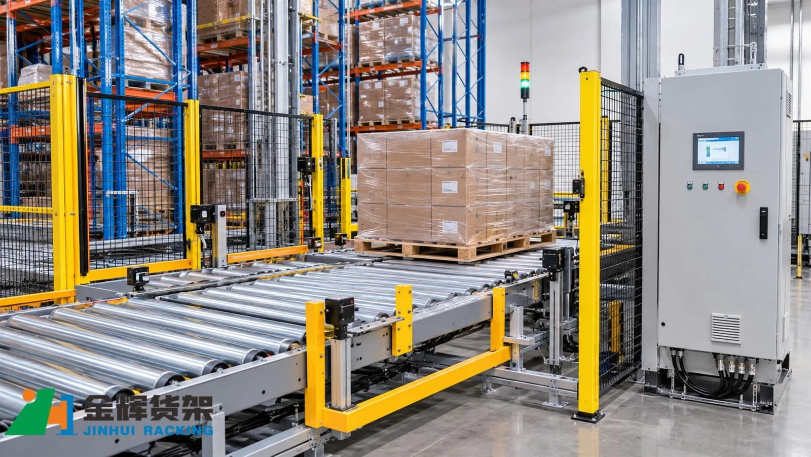
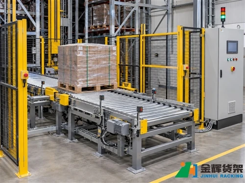
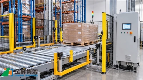
ASRS Conveyor Transfer Station with Pallet Position Detection and Control Equipment
1. Understand the Function of an ASRS Transfer Station
A transfer station is a defined handover point where a pallet moves from one piece of automated handling equipment to another. Its design depends on the system layout, pallet characteristics, equipment type, and required material flow.
Common transfer arrangements include:
- Inbound conveyor to ASRS: Pallets arrive from receiving or production and are prepared for automated storage.
- ASRS to outbound conveyor: Retrieved pallets are transferred toward picking, staging, or dispatch areas.
- Conveyor to lift: A pallet is positioned for transfer between different warehouse levels.
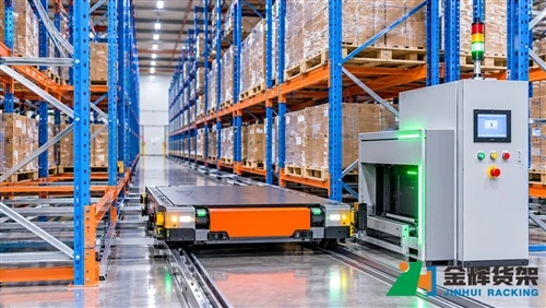
- Conveyor to shuttle system: Pallets are handed over to compatible shuttle equipment through a designated transfer point.
- Conveyor-to-conveyor transfer: Pallets move between connected conveyor sections or different handling directions.
Each arrangement requires a defined transfer sequence. The equipment on both sides must agree that the receiving position is available, the pallet is correctly positioned, and the transfer can proceed safely.
Before commissioning begins, engineers should review the mechanical layout, equipment interface drawings, electrical schematics, PLC I/O list, and control sequence documentation.
2. Check the Mechanical Installation and Pallet Stop Position
The mechanical condition of a transfer station directly affects the accuracy and repeatability of pallet positioning. Sensors and control software cannot compensate for an incorrectly installed conveyor, unsuitable guide arrangement, or inconsistent mechanical stop position.
2.1 Verify conveyor alignment
Inspect the conveyor section and its connection to the adjacent equipment. Confirm that the transfer surfaces are aligned according to the approved engineering drawings.
Typical inspection points include:
- Conveyor frame position and level
- Roller or chain conveyor alignment
- Transfer height relative to the receiving equipment
- Guide rail position and clearance
- Mechanical stops and pallet locating components
- Fixing points, supports, and connection hardware
Any height difference or alignment deviation should be measured against the project tolerances. Do not assume that a pallet will transfer correctly simply because the conveyor sections appear visually aligned.
2.2 Verify the pallet stopping position
The pallet must stop within the transfer station's approved positioning window. Its final location should be suitable for the next handling operation, whether that involves a lift, shuttle, stacker crane, or another conveyor.
Commissioning engineers should verify:
- The pallet reaches the intended stopping position.
- The pallet remains stable after the conveyor stops.
- The pallet is correctly positioned relative to the transfer interface.
- Mechanical locating devices, where provided, operate as designed.
- The pallet does not interfere with guards, sensors, or adjacent equipment.
Use the approved reference points and dimensional tolerances from the project drawings. The acceptable stop-position window may differ between transfer-station designs and pallet-handling equipment.
2.3 Test repeatability
A single successful transfer does not establish that a station is correctly commissioned. Repeated tests should confirm that the pallet stops consistently within the permitted positioning range.
Where the system handles different approved pallet types, test representative loads and dimensions according to the commissioning plan. Record any variation in stopping position and investigate unexpected differences before proceeding to integrated operation.
3. Verify Sensor Installation and Detection Logic
Sensors provide the control system with information about pallet presence, position, transfer status, and equipment availability. Their installation and logic must be checked together because a correctly installed sensor can still produce an incorrect control sequence if its signal is interpreted incorrectly.
3.1 Identify the sensors used at the station
Depending on the transfer-station design, the equipment may use photoelectric sensors, proximity sensors, position switches, or other detection devices.
Typical detection functions include:
- Pallet entry detection: Indicates that a pallet has entered the conveyor section.
- Pallet positioning detection: Confirms that the pallet has reached the designated stopping area.
- Transfer-zone occupancy: Indicates whether the handover area is occupied.
- Equipment position detection: Confirms that a lift, shuttle, or transfer mechanism is in the required position.
- Stopper position feedback: Confirms the status of a movable mechanical stop where fitted.
The actual sensor arrangement should follow the approved equipment design. Not every transfer station requires all of these devices.
3.2 Confirm sensor mounting and detection range
Inspect each sensor's mounting position, orientation, cable routing, and physical protection. Confirm that the sensing area is suitable for the pallet and load configuration.
For photoelectric sensors, check that the intended target can be detected under the actual operating conditions. Reflective wrapping, gaps in the pallet structure, irregular cartons, and changes in load dimensions may affect detection depending on the sensor type and installation.
For proximity sensors or position switches, verify that the intended metal target or mechanical actuator reaches the specified sensing position.
3.3 Test sensor response through the PLC
During commissioning, compare the physical sensor condition with the corresponding PLC input status. Confirm that each input changes as expected when the pallet or mechanism reaches the relevant detection point.
Record the following information for each sensor:
- Sensor identification and location
- Intended detection function
- Normal signal state
- PLC input address or tag
- Observed response during testing
- Any abnormal or unstable detection behavior
Sensor testing should be performed using the approved commissioning method. Safety devices must never be bypassed to make a transfer sequence operate.
4. Check Equipment Handshake Signals
Equipment handshake signals coordinate the actions of connected machines. They establish when one device is ready to receive a pallet, when another device is permitted to transfer it, and when the handover has been completed.
The exact signal names and sequence depend on the PLC architecture and equipment supplier. However, many automated transfer interfaces use signal functions similar to the following.
| Example signal function | Purpose | Typical verification point |
|---|---|---|
| Ready | Indicates that the receiving equipment is available for a transfer. | Confirm that the receiving device is in the required operating state. |
| Occupied | Indicates that a transfer position or zone is occupied. | Compare the signal with the physical pallet presence condition. |
| Transfer Request | Requests a pallet movement between connected equipment. | Confirm that the request is generated only under the configured conditions. |
| Transfer Enable | Permits the transfer when the required interlocks are satisfied. | Verify that both sides meet the approved transfer conditions. |
| Transfer Complete | Confirms that the handover has reached its defined completion state. | Check that completion corresponds to the actual pallet position and sequence. |
| Fault or Not Ready | Indicates that the transfer cannot proceed normally. | Verify that the fault state prevents an unsafe or conflicting movement. |
These are illustrative signal functions, not a universal interface standard. The project-specific signal list and interface control document must define the actual names, electrical characteristics, communication method, and signal ownership.
4.1 Verify the receiving equipment's Ready status
Before a pallet is transferred, the receiving equipment should confirm that it is in an appropriate state to accept the load.
Depending on the design, this may require confirmation that:
- The receiving conveyor or transfer device is available.
- The destination position is not occupied.
- The receiving mechanism is in the correct transfer position.
- No active fault or safety-related stop prevents movement.
- The equipment is in the correct automatic operating mode.
Commissioning should confirm that the Ready signal cannot be generated when the required conditions are not satisfied.
4.2 Verify the transfer request and permission sequence
When a pallet is ready for handover, the sending equipment may issue a transfer request. The receiving equipment then checks its availability and returns the required permission or enable signal.
Test the sequence from both sides of the interface. Confirm that a transfer request is not interpreted as permission to move unless the required receiving conditions are satisfied.
4.3 Verify transfer completion
Transfer completion should be based on the project's defined confirmation conditions. Depending on the design, these may include pallet position feedback, a receiving-zone sensor, or an equipment status signal.
Check that the sending equipment does not release the transfer sequence prematurely and that the receiving equipment does not report a completed handover before the pallet reaches the required position.
5. Test the Complete Transfer Sequence
After individual mechanical, sensor, and interface checks have been completed, perform an integrated transfer test. The purpose is to verify that the connected equipment works as one coordinated system.
A typical illustrative test sequence may include:
- The sending conveyor receives a pallet.
- The pallet moves toward the designated transfer position.
- The positioning sensor confirms that the pallet has reached the required location.
- The sending equipment issues a transfer request according to the configured sequence.
- The receiving equipment confirms that it is ready and the transfer conditions are satisfied.
- The transfer movement is enabled.
- The pallet moves into the receiving equipment's designated zone.
- The receiving position is confirmed through the configured detection logic.
- The transfer-complete condition is communicated to the relevant control equipment.
- The system updates the equipment states and becomes ready for the next task.
This sequence is a general example only. Some systems use hardwired I/O, while others exchange status information through industrial communication networks. The actual sequence must follow the project's approved control design.
5.1 Test normal pallet transfers
Run representative pallet transfers through the station and verify that each stage occurs in the correct order.
Observe the pallet's movement, sensor status, equipment state, and control-system response. Record any unexpected delay, repeated stop, incomplete handover, or disagreement between physical conditions and displayed status.
5.2 Test different approved load conditions
Where the system is designed for multiple pallet sizes or load configurations, test the representative combinations specified in the commissioning plan.
Pay attention to pallet stability, sensor detection, guide clearance, transfer height, and final stop position. Loads must remain within the approved equipment limits during testing.
5.3 Verify upstream and downstream coordination
A transfer station should not be tested only as an isolated machine. Its operation depends on the equipment before and after the handover point.
Confirm that upstream equipment does not send another pallet into an occupied transfer zone and that downstream equipment can receive the pallet without creating a conflicting movement.
6. Test Fault Handling and Blockage Recovery
Commissioning should include controlled tests of abnormal conditions. These tests help confirm that the system detects faults, prevents conflicting movements, and provides useful information for recovery.
Potential test scenarios include:
- Receiving equipment not ready: Confirm that the sending equipment does not start an unauthorized transfer.
- Transfer zone occupied: Verify that another pallet cannot enter a blocked zone.
- Sensor signal missing: Confirm that the system identifies an incomplete or unexpected detection condition.
- Transfer timeout: Verify that the configured timeout response generates an appropriate alarm or fault state.
- Equipment fault during handover: Check that connected equipment responds according to the approved fault-handling sequence.
- Communication interruption: Where applicable, verify that loss of the equipment interface is handled according to the control design.
6.1 Verify the recovery procedure
When a transfer fails, operators should be able to identify the affected equipment, understand the displayed fault, and follow an approved recovery procedure.
The recovery procedure should define:
- How to identify the affected transfer station and pallet.
- Which equipment must remain stopped during inspection.
- How to check the pallet's physical position.
- Which fault conditions require maintenance intervention.
- How to confirm that the transfer zone is safe and clear.
- Who is authorized to reset faults and resume automatic operation.
Do not use forced PLC signals, bypassed interlocks, or manual movement outside the approved recovery procedure. Any work involving hazardous movement or access to guarded equipment must follow the site's isolation and safety requirements.
7. Complete FAT and SAT Commissioning Tests
Factory Acceptance Testing (FAT) and Site Acceptance Testing (SAT) provide structured opportunities to verify the transfer station before shipment and after installation.
7.1 Factory Acceptance Testing (FAT)
FAT is generally carried out before the equipment is delivered to the project site. Its scope depends on the contract and the extent to which the supplier can assemble and simulate the complete system.
Typical transfer-station FAT checks may include:
- Review of mechanical assembly and equipment dimensions
- Inspection of sensor installation and wiring
- PLC I/O checks and signal identification
- Simulation of Ready, Occupied, Request, and Complete states where applicable
- Verification of normal transfer sequences
- Testing of selected fault and timeout conditions
- Review of alarm messages and operating documentation
7.2 Site Acceptance Testing (SAT)
SAT verifies the equipment after installation and connection to the actual warehouse system. It should confirm that the transfer station works correctly with the site's conveyors, ASRS equipment, electrical supply, network, and control software.
Typical SAT checks may include:
- Final conveyor alignment and mechanical positioning
- Actual pallet stopping-position measurements
- Sensor response under site operating conditions
- End-to-end equipment handshake tests
- Communication with the WCS or other control equipment
- Integrated inbound and outbound transfer trials
- Selected fault recovery and restart tests
- Operator and maintenance team training
7.3 Record test results and outstanding issues
Each commissioning test should have a documented result. A useful test record includes the test ID, equipment reference, test condition, expected response, observed result, pass or fail status, and any corrective action.
Outstanding issues should be assigned to a responsible person and tracked until they are resolved and retested. Acceptance should follow the contractual criteria and the approved project commissioning plan.
8. Common Commissioning Mistakes to Avoid
Several commissioning issues can be avoided by checking mechanical, electrical, and software interfaces together rather than treating them as separate tasks.
Checking sensors without testing the complete sequence
A sensor may respond correctly in isolation while the overall transfer sequence remains incorrect. Always verify the relationship between physical detection, PLC logic, equipment status, and the actual pallet movement.
Using assumed signal definitions
Signal names such as Ready or Transfer Complete can have different meanings between suppliers. Use the approved interface documentation rather than assuming that connected machines interpret the signals identically.
Ignoring stop-position repeatability
A successful single transfer does not prove that the station can repeatedly position pallets within the required tolerance. Repeatability should be included in the commissioning test plan.
Testing only normal operating conditions
Fault handling is part of commissioning. The system should be tested under approved abnormal conditions to confirm that occupied zones, missing signals, and equipment faults are handled correctly.
Leaving documentation until the end
Unrecorded changes to sensor positions, PLC tags, or interface logic make future maintenance more difficult. Update the relevant drawings, I/O lists, parameter records, and test documents as commissioning progresses.
Conclusion
Reliable ASRS conveyor transfer-station operation depends on accurate mechanical positioning, consistent sensor detection, and correctly coordinated equipment handshake signals. Commissioning should verify the complete handover process rather than focusing on individual components alone.
By checking conveyor alignment, stop-position repeatability, sensor response, interface logic, fault recovery, and FAT/SAT results, project teams can identify integration issues before normal warehouse operation begins.
The final commissioning criteria should always be based on the approved project drawings, equipment specifications, control documentation, and contractual acceptance requirements.
Contact Us for ASRS Conveyor and Automated Warehouse Solutions
Are you planning an ASRS warehouse project or integrating conveyors with automated storage equipment? JINHUI RACK provides customized warehouse storage solutions that can integrate racking, stacker cranes, shuttle systems, conveyor equipment, and warehouse control systems according to project requirements.
Contact our team to discuss your warehouse layout, pallet specifications, transfer-station requirements, automation interfaces, and commissioning needs.
- Email: info@jhrack.com
- WhatsApp: +86 185 0252 7163
Explore our solutions:
Share your warehouse dimensions, pallet load, required throughput, and automation configuration with our team to discuss a suitable ASRS solution.