ASRS Conveyor Transfer-Station Commissioning: Stop Position, Sensor Logic and Equipment Handshake Tests
An automated storage and retrieval system (ASRS) depends on reliable communication and physical coordination between storage equipment, conveyors, lifts, transfer stations, and control software. Among these interfaces, the conveyor transfer station plays an important role because it is where pallets are received, positioned, checked, and handed over to another piece of equipment.
A transfer station may appear mechanically simple, but incorrect stopping positions, poorly adjusted sensors, or incomplete control signals can interrupt the entire material-handling sequence. A pallet that stops too early or too late may not be transferred correctly. A sensor that reports an incorrect status may prevent the next machine from accepting the load. A missing handshake signal can leave two connected machines waiting for each other.
Commissioning should therefore verify both mechanical positioning and control-system coordination. This guide explains the main checks involved in ASRS conveyor transfer-station commissioning, from stop-position verification and sensor testing to equipment handshake validation and final acceptance.
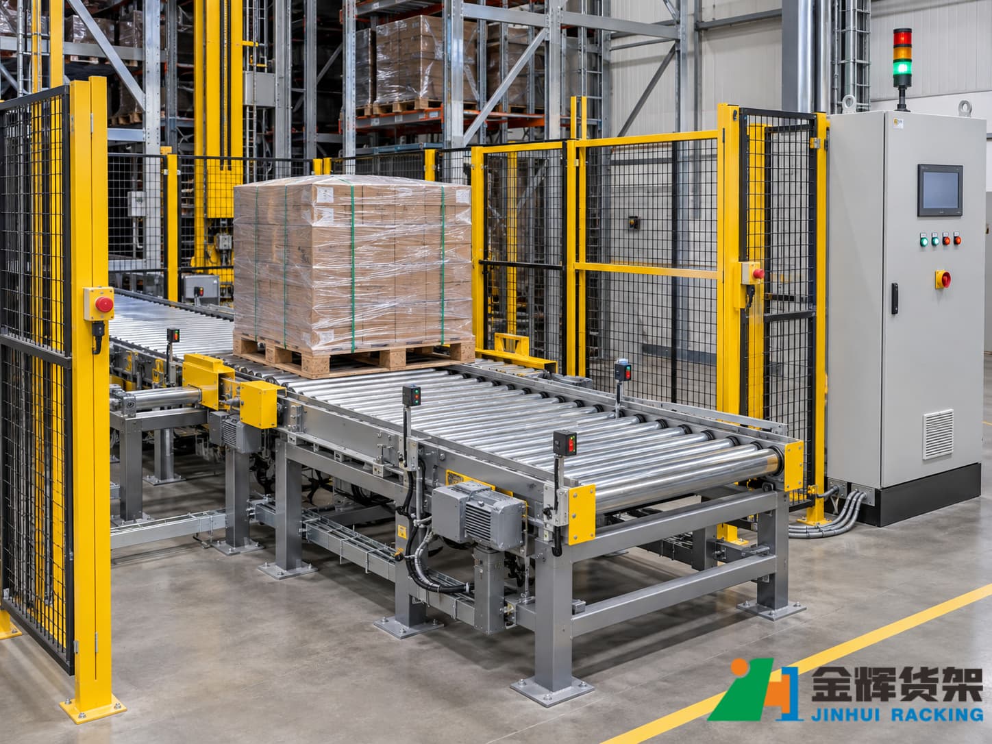
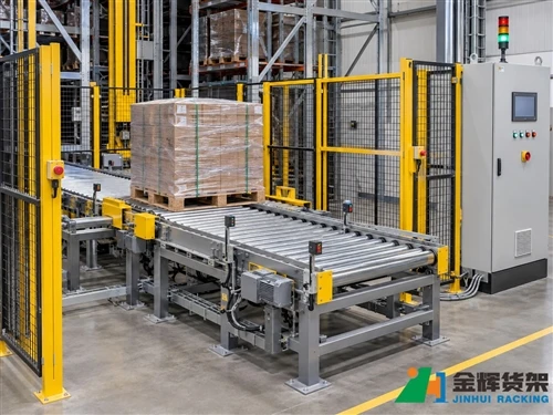
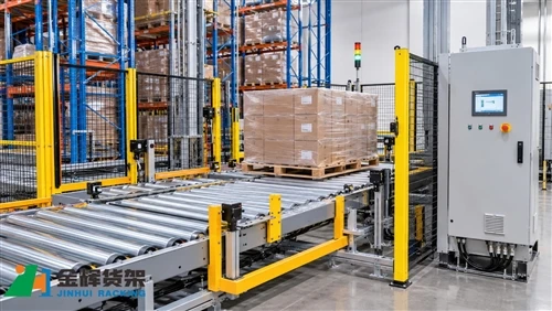
ASRS Conveyor Transfer Station with Pallet Positioning and Control Equipment
1. Understand the Transfer Station's Role in an ASRS
An ASRS conveyor transfer station provides a controlled interface between different material-handling sections. Depending on the project design, it may connect an inbound conveyor, outbound conveyor, storage crane, vertical lift, shuttle system, or another automated handling device.
A typical transfer sequence may involve the following stages:
- A pallet arrives at the designated conveyor section.
- Arrival sensors detect the pallet and report its presence.
- The conveyor moves the pallet toward the defined stopping position.
- A positioning or stop mechanism helps establish the required pallet location, where included in the design.
- The station verifies that the pallet is in the required transfer condition.
- The receiving equipment confirms that it is ready to accept the pallet.
- The transfer operation takes place under the approved control sequence.
- The system confirms transfer completion and updates the relevant equipment status.
The exact sequence depends on the conveyor layout, mechanical design, PLC program, and communication architecture. During commissioning, the project team should use the approved electrical drawings, I/O list, control narrative, and interface documents as the reference for testing.
2. Verify Mechanical Stop Position and Pallet Alignment
Correct pallet positioning is one of the first conditions to verify during transfer-station commissioning. The pallet must stop within the position tolerance required by the receiving equipment.
Even when a conveyor can move a pallet successfully, an incorrect stopping position may cause problems during handover. The pallet may not align with a lift platform, transfer carriage, storage crane interface, or downstream conveyor.
2.1 Confirm the reference position
Before testing, identify the defined pallet reference point and the specified stop position from the approved mechanical layout and commissioning documents.
Depending on the project, the reference may be based on a pallet edge, centerline, mechanical datum, or another documented measurement point. All measurements should use the same reference method to avoid inconsistent results.
2.2 Check conveyor and stop-device alignment
Inspect the transfer station's mechanical arrangement before running automatic sequences. Relevant checks may include:
- Conveyor frame alignment and levelness
- Roller or chain conveyor positioning
- Transfer interface height and alignment
- Mechanical stop or positioning-device location, where fitted
- Guide rail and pallet guide alignment
- Clearance between moving equipment and fixed structures
- Fasteners, supports, and guarding installation
Any dimensional acceptance limits must come from the approved project drawings and equipment specifications. Do not apply a universal stop-position tolerance to every conveyor installation.
2.3 Test pallet stopping repeatability
After the initial alignment check, run controlled positioning tests using the approved test pallet or load configuration.
Record the stopping position across repeated cycles and compare the measurements with the project's acceptance criteria. Testing should cover the relevant operating directions and transfer interfaces.
If the stopping position varies unexpectedly, investigate the mechanical and control causes before adjusting the system. Possible areas include sensor location, conveyor speed, braking behavior, mechanical play, pallet condition, and control timing.
3. Test Sensor Locations and Detection Logic
Sensors provide the control system with information about pallet presence, position, movement, and equipment status. Their correct installation and logic are essential for safe and reliable transfer operations.
The actual sensor types and quantities vary by project. A station may use photoelectric sensors, proximity sensors, limit switches, or other detection devices according to its mechanical and electrical design.
3.1 Verify sensor installation
Inspect each sensor against the approved electrical drawings and I/O list. Confirm that:
- The sensor is installed at the specified location.
- The detection area is appropriate for the intended target.
- The mounting bracket is secure.
- Cables and connectors are protected and correctly routed.
- The sensor indicator responds as expected during a controlled test.
- The PLC input corresponds to the correct sensor tag.
For photoelectric sensors, check that the beam path is not obstructed by structural components or unrelated equipment. For proximity sensors, confirm that the intended target material and detection distance are compatible with the selected sensor.
3.2 Verify pallet-present and position signals
Each detection signal should be tested individually before the complete automatic sequence is enabled.
For example, a station may use separate signals for pallet arrival, pallet-at-stop position, and downstream transfer clearance. The commissioning team should confirm that each signal changes state only under its intended physical condition.
A useful test record includes:
- Sensor tag and physical location
- Expected detection condition
- Observed sensor indication
- Corresponding PLC input status
- Expected control response
- Test result and any corrective action
3.3 Check signal behavior during pallet movement
Static sensor checks alone are not sufficient. The commissioning team should also observe the sensor sequence while a pallet moves through the transfer station.
Confirm that the signals change in the expected order and that the control program responds correctly to the transitions. Unexpected signal overlap, delayed detection, or a signal that remains active after the pallet has moved away may indicate a sensor-positioning, wiring, configuration, or logic issue.
4. Validate the Equipment Handshake Sequence
Equipment handshaking is the exchange of status and command signals between connected machines. It allows one device to confirm that it is ready before another device starts a transfer operation.
In an ASRS conveyor system, the transfer station may exchange signals with a storage crane, lift, shuttle system, or adjacent conveyor controller. The specific signal names and communication method must follow the approved project interface documentation.
4.1 Understand common handshake states
Depending on the project design, the interface may include signals or status states equivalent to the following:
- Ready: The receiving equipment is available to accept a pallet.
- Occupied: A pallet is present at the relevant station or transfer position.
- Transfer Request: A transfer operation has been requested.
- Transfer Enable: The required conditions have been satisfied and transfer is permitted.
- Transfer Complete: The transfer has finished and the required completion condition has been confirmed.
- Fault: A fault or abnormal condition prevents normal operation.
These are illustrative functional descriptions, not universal PLC tag names. Some projects use different terminology, combined status words, fieldbus data, or more detailed state machines.
4.2 Test the receiving equipment's Ready condition
Before the sending conveyor begins a transfer, verify that the receiving equipment reports the correct ready status.
During testing, confirm that:
- The receiving station is in the required operating mode.
- The transfer area is available and not occupied by another pallet.
- Required mechanical devices are in their permitted positions.
- Relevant safety conditions are satisfied.
- The Ready status is correctly communicated to the sending equipment.
The sending equipment should not initiate a transfer simply because a timer has elapsed. The approved interlock conditions must be satisfied.
4.3 Verify Transfer Request and Transfer Complete
Once the receiving equipment is ready and all required conditions are met, the sending station may issue a transfer request according to the control sequence.
The commissioning team should observe the complete exchange:
- The sending station identifies a pallet requiring transfer.
- The receiving equipment confirms its availability.
- The transfer request is issued.
- The receiving equipment accepts the transfer under the approved logic.
- The pallet moves into the receiving position.
- The required position or occupancy condition is detected.
- The transfer-complete status is returned.
- Both equipment sections update their operating states.
Check that the transfer-complete condition is based on the defined feedback signals rather than an assumed travel time alone, unless the approved design explicitly specifies a different method.
4.4 Check signal reset and the next cycle
After a successful transfer, confirm that temporary request and completion signals reset according to the documented sequence. The station should return to the correct state for the next pallet.
A signal that remains active after a completed transfer may block the next cycle or cause the control system to interpret the station as occupied. Verify both normal signal transitions and the reset conditions.
5. Verify Safety Interlocks and Operating Modes
Commissioning must include the safety functions associated with the transfer station. Mechanical movement, conveyor drives, transfer devices, and access points should be tested against the approved risk assessment and safety design.
Depending on the installation, relevant safety-related devices may include:
- Emergency-stop devices
- Guard-door interlocks
- Safety light curtains or scanners
- Safety relays or safety PLC functions
- Protective guarding and access controls
- Reset and restart-permission controls
Verify that the relevant safety devices produce the intended safe response under the documented test procedure. A safety function should not be considered acceptable solely because its indicator light changes state.
Manual, maintenance, and automatic modes should also be checked according to the machine's operating documentation. Confirm that mode selection, access permissions, and movement restrictions behave as specified.
Safety testing must be carried out by qualified personnel using the approved commissioning procedure. Never bypass an interlock or defeat a protective device to complete a production test.
6. Test Fault Handling and Blockage Recovery
A transfer station should be evaluated not only under normal operating conditions but also under defined abnormal scenarios. These tests help confirm that the system detects faults, stops or inhibits the appropriate movement, and provides useful diagnostic information.
Possible commissioning scenarios include:
- A pallet does not reach the expected stop position.
- A pallet-present signal remains active unexpectedly.
- The receiving equipment does not report Ready.
- A transfer request receives no valid response.
- The transfer-complete signal is not received within the configured monitoring period.
- A protective access device is activated.
- A conveyor drive reports a fault.
For each scenario, verify the expected machine response, alarm message, fault identification, and recovery conditions.
6.1 Verify fault identification
Alarm messages should help operators identify the affected station and the type of abnormal condition. Where the control system supports detailed diagnostics, confirm that the displayed alarm corresponds to the actual fault condition.
6.2 Verify recovery permissions
Before a blocked station is returned to operation, the cause of the fault must be identified and addressed. Confirm that the documented recovery procedure includes any required inspection, clearance confirmation, manual movement restrictions, and authorized reset steps.
Resetting an alarm should not automatically restart equipment if the original cause remains unresolved or if a separate restart authorization is required.
7. Complete FAT and SAT Commissioning Tests
Factory Acceptance Testing (FAT) and Site Acceptance Testing (SAT) provide structured opportunities to verify the transfer station before shipment and after installation.
The exact scope depends on the contract, project specifications, and system architecture.
7.1 Factory Acceptance Testing
FAT is generally performed before the equipment is delivered to the project site. Where the transfer station and its control system are available for integrated testing, the FAT may include:
- Review of mechanical assembly and component installation
- Verification of electrical drawings and I/O mapping
- Individual sensor and actuator checks
- Conveyor direction and movement checks
- Pallet stopping and positioning tests
- PLC sequence and handshake simulation
- Alarm and fault-response verification
- Review of operating and maintenance documentation
Where full site interfaces are unavailable, the FAT should clearly identify which functions were simulated and which require confirmation during SAT.
7.2 Site Acceptance Testing
SAT is carried out after installation at the warehouse site. It should verify that the transfer station works correctly with the actual connected equipment and site control network.
Typical SAT activities may include:
- Inspection of installation alignment and mechanical connections
- Verification of field wiring and network communication
- Confirmation of actual sensor detection and PLC input states
- Testing of pallet stopping positions with the agreed test loads
- Integrated handshaking with upstream and downstream equipment
- Verification of operating modes and safety functions
- Testing of defined fault and recovery scenarios
- Recording of results, outstanding issues, and corrective actions
Where the project includes WMS or WCS integration, the relevant order, equipment-status, and material-flow interfaces should also be tested according to the agreed integration scope.
8. Example ASRS Transfer-Station Commissioning Checklist
The following checklist can be adapted for project use. Actual acceptance limits and test methods must be taken from the approved project documentation.
| Inspection area | Commissioning check | Expected evidence |
|---|---|---|
| Mechanical installation | Check frame, conveyor, guides, and transfer interface alignment | Inspection record and dimensional results |
| Stop position | Measure pallet stopping position across repeated cycles | Recorded measurements within project tolerance |
| Sensor installation | Verify sensor location, target detection, and mounting | Sensor inspection and functional test results |
| PLC I/O | Confirm field-device signals correspond to the correct PLC tags | Completed I/O test sheet |
| Handshake | Test Ready, Occupied, Request, and Completion states as defined by the project | Recorded interface sequence |
| Safety functions | Test emergency stops, guards, and relevant protective devices | Approved safety-function test records |
| Fault handling | Test defined abnormal conditions and recovery permissions | Alarm and recovery test records |
| Integrated operation | Run complete transfer cycles with connected equipment | Successful integrated test results |
| Documentation | Review drawings, parameter records, test sheets, and outstanding issues | Completed commissioning dossier |
9. Common Commissioning Mistakes to Avoid
Several issues can reduce commissioning efficiency or create problems after the system enters operation.
9.1 Testing sensors without testing the complete sequence
A sensor may work correctly in an individual test but still produce an unexpected result during automatic operation. Always verify the complete pallet movement and signal sequence.
9.2 Adjusting stopping positions without checking the mechanical reference
Changing a sensor position or PLC parameter without confirming the mechanical datum may hide the original problem. Establish the correct physical reference before making adjustments.
9.3 Treating handshake signals as independent status lights
Ready, Request, and Transfer Complete signals are part of a coordinated control sequence. Test their timing, dependencies, reset behavior, and response to abnormal conditions.
9.4 Accepting simulated tests as full site integration
Simulated FAT results are useful, but they do not replace tests with the actual connected equipment and site network. Clearly identify which tests remain open for SAT.
9.5 Ignoring alarm and recovery behavior
A station that works under normal conditions may still cause extended downtime if its alarms are unclear or its recovery sequence is incomplete. Include fault scenarios in the commissioning plan.
Conclusion
Successful ASRS conveyor transfer-station commissioning requires more than confirming that the conveyor can move a pallet. The project team must verify mechanical alignment, repeatable stop positions, sensor detection, PLC I/O mapping, equipment handshake sequences, safety functions, and fault recovery behavior.
FAT and SAT should provide clear evidence that the transfer station meets the approved project requirements and can communicate reliably with upstream and downstream equipment. A structured commissioning checklist also helps reduce interface problems and provides a useful reference for future maintenance.
Contact Us for ASRS Conveyor and Automated Storage Solutions
Are you planning an ASRS project or integrating conveyor transfer stations into an existing automated warehouse? JINHUI RACK can help you evaluate storage layouts, pallet handling requirements, conveyor interfaces, and automated storage configurations.
Contact our team to discuss your warehouse project, equipment connection requirements, and customized storage solutions.
- Email: info@jhrack.com
- WhatsApp: +86 185 0252 7163
To help us understand your project, share the warehouse layout, pallet specifications, conveyor arrangement, connected equipment, and required material-handling capacity.