Seismic Design Inputs for Warehouse Pallet Racking: Site Parameters, Load Cases and Anchorage Checks
Warehouse pallet racking is a structural storage system that must support stored goods, handling equipment, and operational loads throughout its service life. In regions exposed to earthquakes, rack design requires additional engineering consideration because seismic forces can cause horizontal movement, structural deformation, connection forces, and overturning effects.
Seismic design should not begin with selecting a rack beam or upright size alone. Engineers first need to understand the warehouse location, applicable design standards, building conditions, rack configuration, stored pallet loads, and floor anchorage requirements. These inputs form the basis of structural calculations and help determine whether the proposed racking system is suitable for the project.
This guide explains the main information required for warehouse pallet rack seismic design, including site parameters, structural load cases, rack configuration, base plate connections, anchor bolts, and concrete floor conditions.

Structural Components and Anchorage Considerations for Seismic Pallet Rack Design
1. Why Seismic Design Matters for Warehouse Pallet Racking
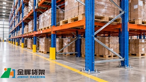
Warehouse pallet racks are generally constructed from interconnected steel uprights, beams, bracing members, base plates, and anchoring components. Their structural behavior depends on the rack geometry, connection characteristics, loading conditions, and support conditions at the warehouse floor.
During an earthquake, stored goods and rack structures are subjected to dynamic horizontal movement. The resulting forces can affect several parts of the storage system:
- Upright frames: Horizontal seismic forces may increase bending and axial demands on vertical members.
- Beam-to-upright connections: Connection forces and rotational behavior influence the overall structural response.
- Bracing members: Diagonal and horizontal bracing helps provide structural stability and resist lateral loads.
- Base plates: The connection between rack uprights and the floor must transfer the required forces.
- Anchor bolts: Anchors may be subjected to tension, shear, and combined loading.
- Stored pallets: Pallet loads may move, shift, or become unstable if storage and restraint arrangements are inadequate.
Seismic performance is therefore not determined by the steel rack alone. It depends on the complete structural system, including its connections, anchorage, stored loads, and supporting concrete floor.
2. Collect the Correct Site and Seismic Design Parameters
The first stage of seismic rack design is to establish the applicable design criteria for the project location. Seismic requirements differ between countries and regions, and even locations within the same country may have different design parameters.
2.1 Warehouse location and applicable design standards
Engineers need the exact project location to identify the relevant building regulations and seismic design standards.
Depending on the country and project requirements, the design may need to consider standards or regulations such as:
- Applicable national building codes and local seismic regulations
- ASCE 7 provisions where the project follows the relevant US design framework
- Eurocode 8 and applicable national annexes for projects using the European design framework
- Relevant steel design standards and specialized industrial storage rack requirements
- Project-specific engineering specifications and owner requirements
The applicable standard should be confirmed before structural calculations begin. Different standards may use different seismic parameters, load combinations, structural classifications, and acceptance criteria.
2.2 Seismic hazard information
Depending on the selected design standard, engineers may need information such as:
- Mapped seismic hazard parameters
- Site-specific ground motion information, where required
- Site soil classification or ground type
- Seismic design category or equivalent classification
- Importance or risk category of the facility
- Applicable response modification or behavior factors
These values should be obtained from the applicable code, approved geotechnical information, or a qualified seismic design professional. They should not be estimated from the warehouse address alone.
2.3 Soil and geotechnical conditions
Although pallet racks are normally supported by a concrete floor slab, the condition of the underlying ground can influence the performance of the warehouse foundation and floor system.
Relevant geotechnical information may include soil classification, bearing conditions, groundwater conditions, settlement characteristics, and potential ground-related hazards identified by the project geotechnical investigation.
For larger facilities or projects with demanding seismic requirements, the design team should coordinate the rack anchorage design with the building structural engineer and geotechnical engineer.
3. Define the Pallet Rack Configuration and Structural Geometry
After establishing the site design criteria, engineers need an accurate description of the proposed rack system. Rack geometry and structural arrangement directly affect how seismic forces are distributed through the structure.
3.1 Rack dimensions and layout
The following information should be provided:
- Total rack height
- Bay width and beam span
- Frame depth
- Number of beam levels
- Number of rack rows
- Single-row or back-to-back configuration
- Flue spaces and row spacing, where applicable
- Location of aisles, end frames, and structural connections
The overall warehouse layout is also important because the rack system may interact with building columns, walls, conveyors, automated equipment, and other structures.
3.2 Upright frames and bracing arrangement
Upright frames typically consist of vertical steel columns connected by horizontal and diagonal bracing members. Their configuration influences stiffness, load distribution, and structural stability.
Engineers should confirm:
- Upright section type and dimensions
- Steel material grade and relevant mechanical properties
- Frame bracing arrangement
- Bracing member dimensions and connection details
- Upright perforation pattern and beam connection arrangement
- Base plate dimensions and connection details
Changes to upright profiles, bracing patterns, or connection components may affect the structural model. Substituting components without engineering review can invalidate previously completed calculations.
3.3 Beam and connection information
Beam dimensions and beam-to-upright connections should be documented as part of the structural design input.
Relevant information includes beam section properties, connection geometry, connector details, locking arrangements, and the structural characteristics required by the selected design method.
Where connection behavior influences the structural analysis, engineers should use appropriate test data, manufacturer information, or validated engineering models rather than assuming that all rack connections behave as perfectly rigid or perfectly pinned joints.
4. Establish the Correct Loads and Seismic Load Cases
Seismic design requires more than calculating the weight of an empty rack. Engineers must consider the stored goods, rack components, operational conditions, and applicable combinations of vertical and horizontal actions.
4.1 Dead loads
Dead loads include the permanent weight of the rack structure and other components that remain part of the installation.
Depending on the design scope, these may include:
- Upright frames and bracing members
- Horizontal beams and support components
- Base plates and connection hardware
- Permanent accessories and fixed equipment
- Other permanently installed structural components
4.2 Stored pallet loads
Stored pallet loads are a major consideration because they contribute significantly to the mass of the loaded rack system.
Before design calculations, confirm:
- Maximum pallet gross weight
- Number of pallets per beam level
- Number of loaded storage levels
- Maximum intended bay loading
- Load distribution and pallet support conditions
- Any permitted variations in pallet weight
Engineers should use the project-specific loading arrangement and the requirements of the applicable standard. Assuming that every bay is either completely empty or uniformly loaded may not represent the actual design conditions.
4.3 Horizontal seismic actions
Earthquake-induced horizontal actions can affect rack structures in different directions. The design should consider the applicable seismic directions and load combinations required by the governing standard.
Important factors may include:
- Seismic hazard parameters for the project location
- Structural height and dynamic characteristics
- Effective seismic mass
- Structural classification and behavior factors
- Direction of seismic action
- Applicable vertical seismic effects, where required
The seismic analysis method and load combinations should be selected by qualified structural engineers in accordance with the governing design standard.
4.4 Load combinations
Rack structural calculations should evaluate the combinations of loads required by the applicable code. These may include dead loads, stored loads, seismic actions, and other relevant effects.
Load factors, combination rules, and assumptions must be consistent with the selected standard. Values from different standards should not be combined without a clear engineering basis.
5. Evaluate Rack Stability and Structural Response
Once the geometry and design loads are established, engineers can assess the structural response of the rack system.
5.1 Upright member strength
Uprights are subjected to combinations of axial force and bending effects. Their structural capacity depends on section geometry, material properties, effective length, restraint conditions, and the applicable design method.
Seismic calculations should check whether the resulting member forces remain within the permitted structural resistance limits.
5.2 Frame and bracing stability
Bracing members help maintain frame stability and transfer forces through the rack structure. Engineers should verify the capacity of relevant bracing components and their connections under the design load combinations.
Structural analysis should also consider the overall stability of the rack arrangement, including potential second-order effects where required by the design standard.
5.3 Beam and connector performance
Although beams primarily support pallet loads, their connections also form part of the rack's structural system.
The design review should verify the relevant beam strength, connection resistance, and deformation requirements. Where the structural model relies on connection characteristics, those assumptions should be supported by suitable engineering information.
5.4 Deflection and deformation
Structural performance is not limited to strength. Engineers should also evaluate the deformation and displacement limits required by the project and governing standards.
Excessive movement may affect clearances, connected equipment, pallet stability, and the operation of automated material-handling systems.
6. Check Base Plates and Anchor Bolt Design
Rack anchorage is a critical part of seismic design because the forces developed in the rack structure must be transferred safely to the supporting concrete floor or foundation.
Even if the rack members have sufficient structural capacity, inadequate base plates or anchorage may compromise the performance of the complete installation.
6.1 Base plate verification
Base plates connect the rack uprights to the supporting surface. Their design should be checked for the forces and moments transferred from the upright frame.
Relevant considerations include:
- Base plate dimensions and thickness
- Upright-to-base-plate connection details
- Anchor bolt arrangement
- Applied axial forces and bending moments
- Local bearing and plate deformation
- Compatibility with the supporting concrete
The base plate should be designed as part of the complete load-transfer system rather than treated as an independent fixing accessory.
6.2 Anchor bolt tension and shear
Seismic forces may generate tension and shear demands in rack anchors. Depending on the structural response, anchor bolts may also experience combined loading.
Engineers should verify the relevant anchor resistance according to the applicable concrete and anchorage design requirements.
Potential failure modes that may require evaluation include:
- Steel failure of the anchor
- Concrete breakout
- Pullout resistance
- Concrete pryout
- Edge-related concrete failure
- Combined tension and shear effects
The actual checks depend on the anchor type, installation method, concrete properties, edge distances, spacing, embedment, and governing standard.
6.3 Anchor type and installation conditions
Mechanical anchors and adhesive anchors may have different design characteristics and installation requirements. The selected anchor must be suitable for the calculated loads and the actual concrete conditions.
Before installation, confirm:
- Anchor product and manufacturer specifications
- Approved diameter and embedment depth
- Required edge distance and anchor spacing
- Concrete strength and condition
- Installation method and equipment
- Required inspection and installation records
Anchor installation should follow the approved technical documentation. Replacing a specified anchor with another product of a similar diameter does not automatically provide equivalent structural performance.
7. Verify Concrete Floor and Supporting Conditions
The warehouse floor is part of the rack support system. Seismic anchorage calculations are only reliable when the supporting concrete conditions are properly understood.
7.1 Concrete thickness and strength
Important floor information includes:
- Concrete slab thickness
- Specified concrete compressive strength
- Reinforcement arrangement
- Presence of structural joints
- Distance to slab edges and openings
- Local floor condition and any deterioration
These details affect the available anchorage capacity and the suitability of the proposed anchor layout.
7.2 Reinforcement and embedded services
Before drilling anchor holes, the installation team should consider the location of reinforcement, embedded electrical conduits, pipes, and other services.
Where necessary, existing drawings, reinforcement scanning, or other approved investigation methods should be used to identify potential conflicts.
Cutting reinforcement or relocating anchors without engineering approval may affect the supporting structure and should not be treated as a routine site adjustment.
7.3 Floor joints and slab limitations
Rack base plates should be positioned with consideration for construction joints, expansion joints, control joints, and slab edges.
Anchors installed close to joints or edges may have different resistance characteristics from anchors installed in unrestricted concrete regions. The actual allowable arrangement should be confirmed by the structural engineer.
For racks installed on suspended slabs or elevated floors, additional coordination with the building structural engineer is essential because the supporting structure may have different load and deformation limitations from a ground-supported slab.
8. Consider Rack-to-Building and Operational Interfaces
Warehouse racks are installed within a larger building environment. Their seismic performance and operational requirements should be coordinated with surrounding structures and equipment.
8.1 Clearance from building structures
Confirm the required clearances between rack structures and nearby building columns, walls, ceilings, and other fixed elements.
Seismic movement may reduce available clearance. The design should consider the applicable movement requirements and avoid unintended impact between the rack and surrounding structures.
8.2 Connections to adjacent rack rows
Back-to-back rack arrangements and other connected configurations may include row spacers or additional structural components. Their function and design assumptions should be documented.
Engineers should confirm whether adjacent rows are intended to act independently or as part of a coordinated structural arrangement. Connection details must match the assumptions used in the structural analysis.
8.3 Sprinkler systems and other building services
Rack layouts may interact with sprinkler pipes, fire protection systems, lighting, ventilation equipment, and cable routes.
Seismic movement and rack deformation should be considered when coordinating these interfaces. Fire protection and building service requirements must be reviewed under the applicable regulations and project specifications.
8.4 Automated warehouse equipment
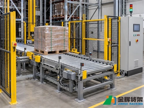
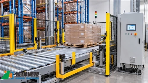
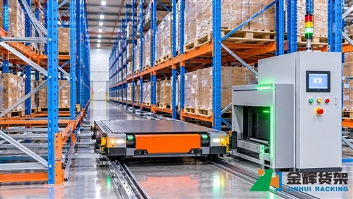
Where pallet racking is integrated with stacker cranes, shuttles, conveyors, or other automated equipment, engineers should also consider equipment clearances, guide arrangements, and interface tolerances.
The structural design should be coordinated with the automation supplier to ensure that the rack's expected deformation and movement remain compatible with the operating requirements of connected equipment.
9. Prepare a Seismic Rack Design Information Checklist
Collecting complete project information at the beginning of the design process helps reduce engineering revisions and installation conflicts.
| Information category | Required project information | Purpose |
|---|---|---|
| Project location | Country, city, site address, applicable regulations | Identify governing seismic design requirements |
| Seismic parameters | Hazard data, site classification, importance category, applicable design factors | Establish seismic design actions |
| Geotechnical data | Soil report, ground conditions, foundation information | Coordinate ground and supporting conditions |
| Rack geometry | Rack height, bay width, frame depth, beam levels, row layout | Develop the structural model |
| Structural components | Upright profiles, beams, bracing, connection details, steel properties | Verify member and connection resistance |
| Stored loads | Pallet weight, loading pattern, number of levels, load distribution | Determine design mass and gravity actions |
| Concrete floor | Slab thickness, concrete strength, reinforcement, joints, edge distances | Verify anchorage and floor suitability |
| Anchorage | Base plate details, anchor type, diameter, embedment and spacing | Check load transfer to concrete |
| Building interfaces | Column locations, wall clearances, services, equipment interfaces | Coordinate movement and installation requirements |
10. Common Mistakes in Seismic Pallet Rack Design
10.1 Using generic seismic parameters
Seismic parameters should be based on the actual project location and governing design standard. Applying values from another warehouse or region without verification may produce an unsuitable design basis.
10.2 Ignoring the actual stored pallet loads
Stored goods contribute to the seismic mass of the rack system. Using incorrect pallet weights or unrealistic loading assumptions can affect the calculated structural demand.
10.3 Treating anchor bolts as standard accessories
Anchors are structural components that transfer forces to the supporting concrete. Their capacity, embedment, spacing, edge distances, and installation conditions should be checked as part of the engineering design.
10.4 Designing the rack without checking the floor
A rack structure may satisfy its member checks while the supporting concrete slab or anchorage arrangement remains inadequate. Floor information should be obtained and reviewed before the final anchorage design is approved.
10.5 Changing rack components without recalculation
Changes to upright sections, bracing arrangements, beam connections, base plates, or anchor details may affect the original design assumptions. Any significant modification should be reviewed by the responsible engineer.
10.6 Ignoring stored-load stability
Structural rack design and pallet stability are related but separate considerations. Suitable pallet dimensions, load distribution, support conditions, and any required retention measures should be reviewed as part of the overall warehouse safety strategy.
Conclusion
Seismic pallet rack design begins with accurate project information. Warehouse location, seismic hazard parameters, site conditions, rack geometry, pallet loads, structural components, and concrete floor details all contribute to the design process.
Engineers must evaluate the complete structural load path, from upright frames and bracing to base plates, anchor bolts, and supporting concrete. Coordination with building engineers, geotechnical professionals, and automation suppliers is also important when racks are integrated into complex warehouse facilities.
By establishing the correct design inputs and verifying each structural interface, warehouse operators and project teams can make better-informed decisions when planning pallet racking installations in earthquake-prone regions.
Contact Us for Warehouse Pallet Racking Solutions
Are you planning a warehouse pallet racking project in an earthquake-prone region? JINHUI RACK can help you evaluate storage requirements, rack configurations, pallet loading conditions, and project-specific installation needs.
Contact our team to discuss your warehouse layout, storage capacity, rack dimensions, and technical requirements. Our team can work with your project information to help identify a suitable pallet racking solution.
- Email: info@jhrack.com
- WhatsApp: +86 185 0252 7163
For an initial project review, please share your warehouse location, rack layout, pallet specifications, maximum storage loads, and available concrete floor information.